FROM MATERIAL TO ASSEMBLY
3D Printed Laboratory Building for Industrialized Construction Education and Research
In collaboration with Camilo Rivas, Zai Shi, Dinorah Martinez Schulte, Artem Egorov, and Taylor Rawlinson
This project proposes a building that embodies industrialized construction principles by integrating a systematic design–to–construction pipeline that advances research and education on industrialized construction practices. The building’s program is organized around six key stages: loading, learning, programming, assembly, experimentation, and exhibition, spatially reflecting the progression from material selection and storage to algorithm development, full-scale fabrication, scientific testing, and communication. Through interdisciplinary academic work, including computational and structural design of wall systems, development of path-generation algorithms for robotic fabrication, and large-scale 3D Concrete Printing (3DCP), the project establishes a repeatable design-to-fabrication framework for industrialized construction. Architecturally, the building incorporates innovations such as 3D printed concrete (3DPC) walls, robot-assembled partition panels, and prefabricated assemblies, demonstrating how new materials, geometries, and regulatory considerations can be systematically integrated into a purpose-built environment. The resulting structure serves as both an advancement in industrialized construction and an open laboratory, making the processes of design, fabrication, and construction legible and actionable, bridging research and practice at the intersection of technology and assembly.
Introduction
Recent research in additive manufacturing has begun focusing on its integration into architecture and construction. 3D Concrete Printing (3DCP) is a fabrication technique that integrates design, fabrication, and construction into a singular workflow, creating new geometries and ways of using the material. 3DCP has shown potential to be used on a larger scale; however, there are some critical challenges related to both material behavior and process logic. Stacking layers of material results in non-uniform mechanical performance that causes weak connections and gaps between layers, affecting structural reliability. It is also important to consider that geometry and environmental conditions, such as evaporation, influence structural strength. The way of building directly influences the shape, performance, and feasibility of the architecture. Labs at Princeton and ETH Zurich have demonstrated how these technological constraints can be translated into spatial and formal strategies.
A number of architectural precedents, such as the Tor Alva tower, Community First Village, House Zero, and Sonsbeek Pavilion, establish a shift from 3DCP as a discrete tool toward understanding it as an integrated architectural system. Learning from these projects informed this paper’s approach to 3DCP wall systems, where geometry and alignment are not only formal decisions but also organize the space and the continuity of the experience.
Motivation
The University of Florida is developing the nation’s first Industrialized Construction Engineering degree program and an accompanying demonstration building. The building showcases multiple industrialized construction methods, including 3D concrete printing, prefabricated modular assemblies, and robotic assembly systems, while also serving as a research facility for advancing these same technologies. This paper focuses primarily on the 3DCP process. Public visibility is a central objective, both for educational purposes and for marketing the new degree program.
Problem Statement
How might we help the construction research team and collaborating industry partners validate the design-to-fabrication processes and performance limits of 3DCP and digital fabrication systems for the construction research laboratory and educational demonstration facility? This project addresses this problem statement by creating a full-scale demonstration that integrates research validation, industry collaboration, and educational infrastructure within a single facility. The building includes a mixed-use high-bay space supporting both indoor and outdoor experimentation, complemented by adjacent offices, instrumentation rooms, collaborative instructional spaces, and service areas.
Methodology
Building Design
The building design is structured as a spatial translation of an industrialized construction workflow, organized into six sequential stages: loading, learning, programming, assembly, experimentation, and exhibition (Fig. 1). These stages become an unconventional program, more similar to an operational framework that defines the building’s spatial organization, circulation, and functional relationships, resulting in three final programmatic blocks: education and learning, production, and exhibition.
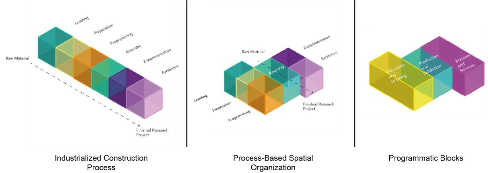
Figure 1. Diagrammatic representation of the industrialized construction process, process-based spatial organization, and programmatic blocks.
Early-stage design decisions were informed by environmental and contextual analysis conducted using Autodesk Forma (Figure 2). Environmental conditions and site constraints were evaluated to establish performance-based parameters that guided initial design decisions. Based on these inputs, we studied different organizations of space and their relationship to both program requirements and environmental performance. Following this evaluation, a base architectural model was established with controlled, uniform walls that serve as primary organizers of space through alignment, spacing, and continuity, without incorporating surface texturing at this stage.
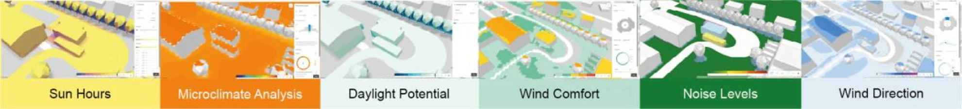
Figure 2. Environmental analysis informing the initial architectural model, including sun exposure, daylight potential, microclimate conditions, wind behavior, and noise levels, is used to establish baseline design parameters.
Introducing 3DCP as a construction logic shifts the design process. Within this framework, walls determine circulation, enclosure, and visibility. Drawing on precedents such as the Sonsbeek Pavilion (Fig. 1), the design adopts a strategy of sequencing planar and curved wall elements, where spatial differentiation emerges through variation in positioning and orientation rather than through formal complexity.
This approach establishes a direct relationship between how a structure is built and how it is organized. The base wall system controls the geometry and accommodates material-specific and computational changes. As a result, the architectural design is defined as an intermediate stage within a broader design-to-fabrication process, where the organization of space is determined before the integration of the material’s geometric complexity (Figure 3).
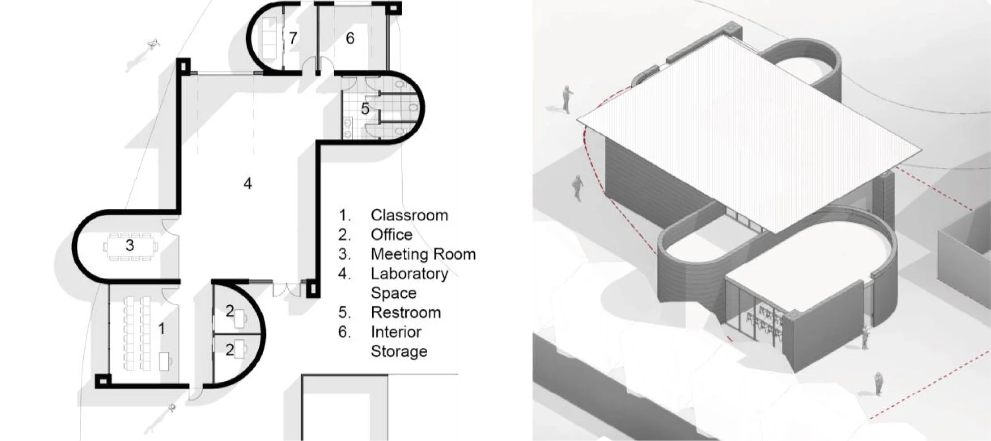
Figure 3. Floor plan and axonometric view of programmatic blocks.
Material Definition
Material Composition
The generic 3D-printed concrete mix is composed of Type IL cement, tap water, locally sourced ASTM C33 #4 fine aggregate, ASTM C33 #89 coarse aggregate, CEMEX D.FAB 3D α. 1.00 superplasticizing admixture, CEMEX ISOXEL 5450 set-accelerating admixture, and D.FAB 3D β. 1.00 stiffening admixture (COBOD), as shown in Figure 4.
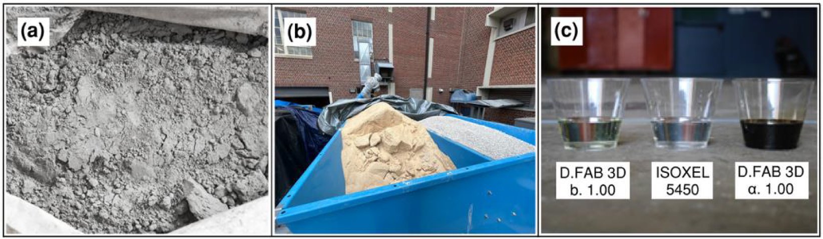
Figure 4. (a) Type 1L cement. (b) ASTM C33 #4 fine aggregate and ASTM C33 #89 coarse aggregate. (c) Admixtures.
Production Process
A precise 2K extrusion system is used to produce the 3DPC mixture, as depicted in Figure 5(a). In this process, the superplasticizing and set-accelerating admixtures are incorporated at the batch plant, while the stiffening admixture is added at the printer hopper. By dosing the superplasticizing admixture at the batch plant, the operator ensures that the mixture remains flowable in the hose. Furthermore, by adding the set accelerator at the batch plant, the material has more time to develop strength, which is crucial for supporting successive layers. The stiffening admixture is dosed at the printer’s extrusion head to improve the material’s cohesiveness and its ability to follow the nozzle’s form.
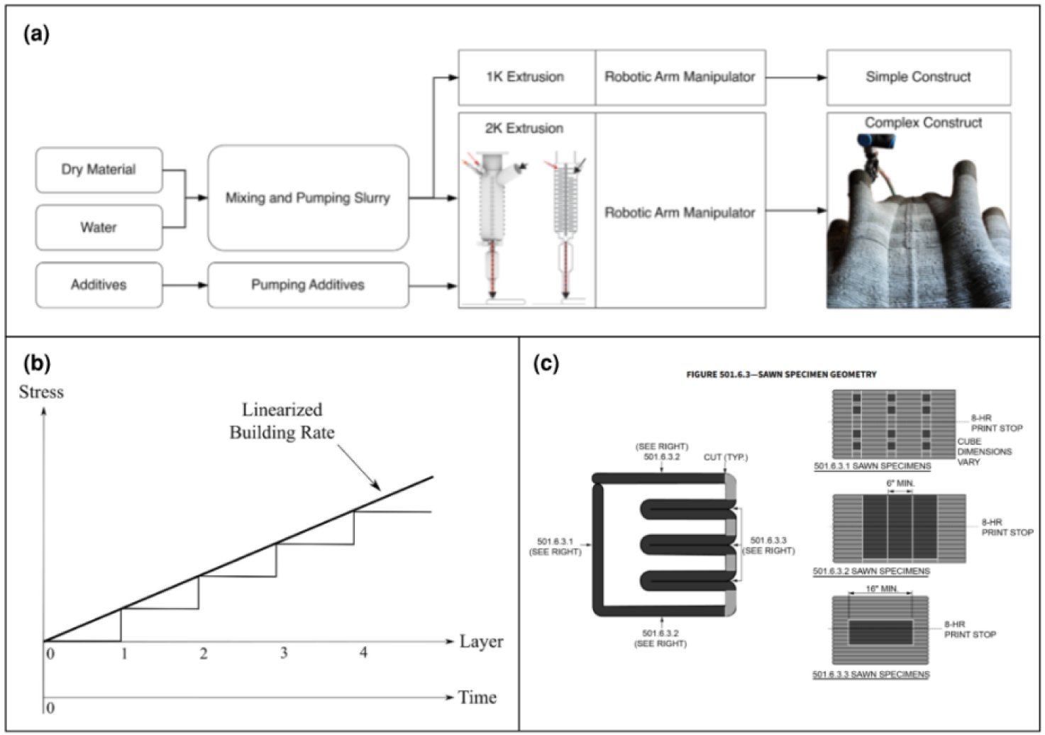
Figure 5. (a) Comparative schematic of 1K and 2K material processes. (b) Schematic showing a linearized stress building rate to simplify model development. (c) ICC 1150 Prequalification element.
Buildability Performance
With the addition of each new layer, the stress in the layers below increases until it exceeds the material’s yield strength, at which point the structure fails. The materials team can predict the number of layers that can be printed without failure by using the buildability model illustrated in Figure 5(b). The material’s buildability performance depends on the quantity and composition of the admixtures used, print speed, and layer geometry.
Laboratory and Field Prequalification Testing and Special Inspections
To comply with a number of codes, such as ICC 1150, the fresh and hardened properties of the material are prequalified in both laboratory and field settings. Fresh property tests evaluate workability, air content, density, and set time, while hardened property tests evaluate compressive strength, shrinkage, and chloride exposure.
Computational Design, Digital Tools, and Fabrication System
The fabrication system implemented in this project is 3DCP, an additive manufacturing process in which cement is deposited layer by layer without molds. In this case, concrete is used as the primary material for load-bearing structural walls, enabling a direct translation of digital geometry into materialized architecture. 3DCP offers significant geometric freedom to create curved or perpendicular walls with surface textures that respond to material behavior and wall orientation. The walls are printed using a COBOD BOD3 printer (Figure 6), a robotic bridge structure that moves tools specifically developed for architectural-scale construction.
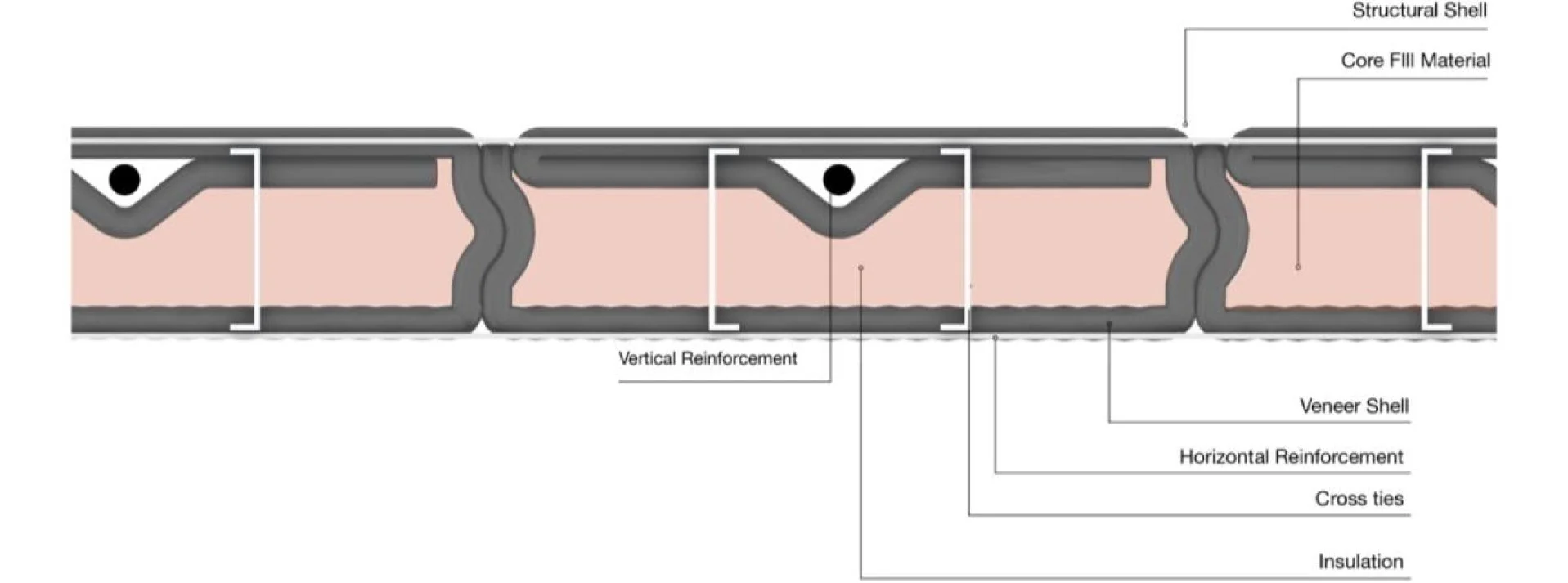
Figure 6. 3DPC wall design.
Given the structural role of the walls, a multi-shell wall system is implemented, consisting of two distinct parts: an interior load-bearing structural shell and an exterior non-load-bearing shell.
As illustrated in Figure 6, the interior shell integrates steel or other supports for added strength, with concrete poured inside the cores, while intentionally maintaining a space for material that slows heat transfer. The exterior shell is non-structural, allowing for controlled surface texture through layer-by-layer material buildup.
Surface texture is defined computationally based on wall orientation and geometry. The curved walls have smoother surfaces compared to the perpendicular walls, which allow for more pronounced textures. A continuous overlap strategy applied across all layers generates a texture gradient from zero overlap to a maximum horizontal displacement of ±25 mm, as detailed in Figure 7. The controlled overlap ensures that the geometry remains consistent and that the material remains stable during printing.
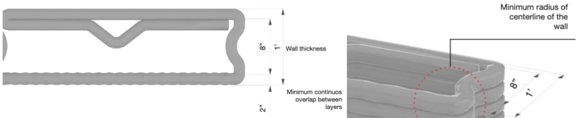
Figure 7. 3DCP wall texture design.
To enable this fabrication logic, a custom computational script for 3D printing is developed.
The workflow begins by tracing the wall profile of both the interior and exterior walls as a single continuous path and then extracting the wall height and thickness from a 3D Revit model. This information is used to generate a continuous helical printing path that stacks layers based on the material thickness, creating the geometry by dividing it into individual points. Each point provides X, Y, and Z coordinates used to generate the G-code. The final printing path is digitally validated before construction using a MeshPipe simulation. All of these steps are part of a single continuous workflow, allowing for better control and alignment between digital design and construction.
Results
Prequalification Element and Digital Rendering of the Building
The results of this study are presented through two complementary components: a physical prequalification element and the architectural projection of the system at the building scale.
The fabricated part serves as a prequalified element under ICC 1150, designed primarily to validate the material and process. In addition to its technical role, the prequalification element helped observe the relationship between geometry and the building method, informing design decisions regarding wall orientation, layer placement, and printing sequence.
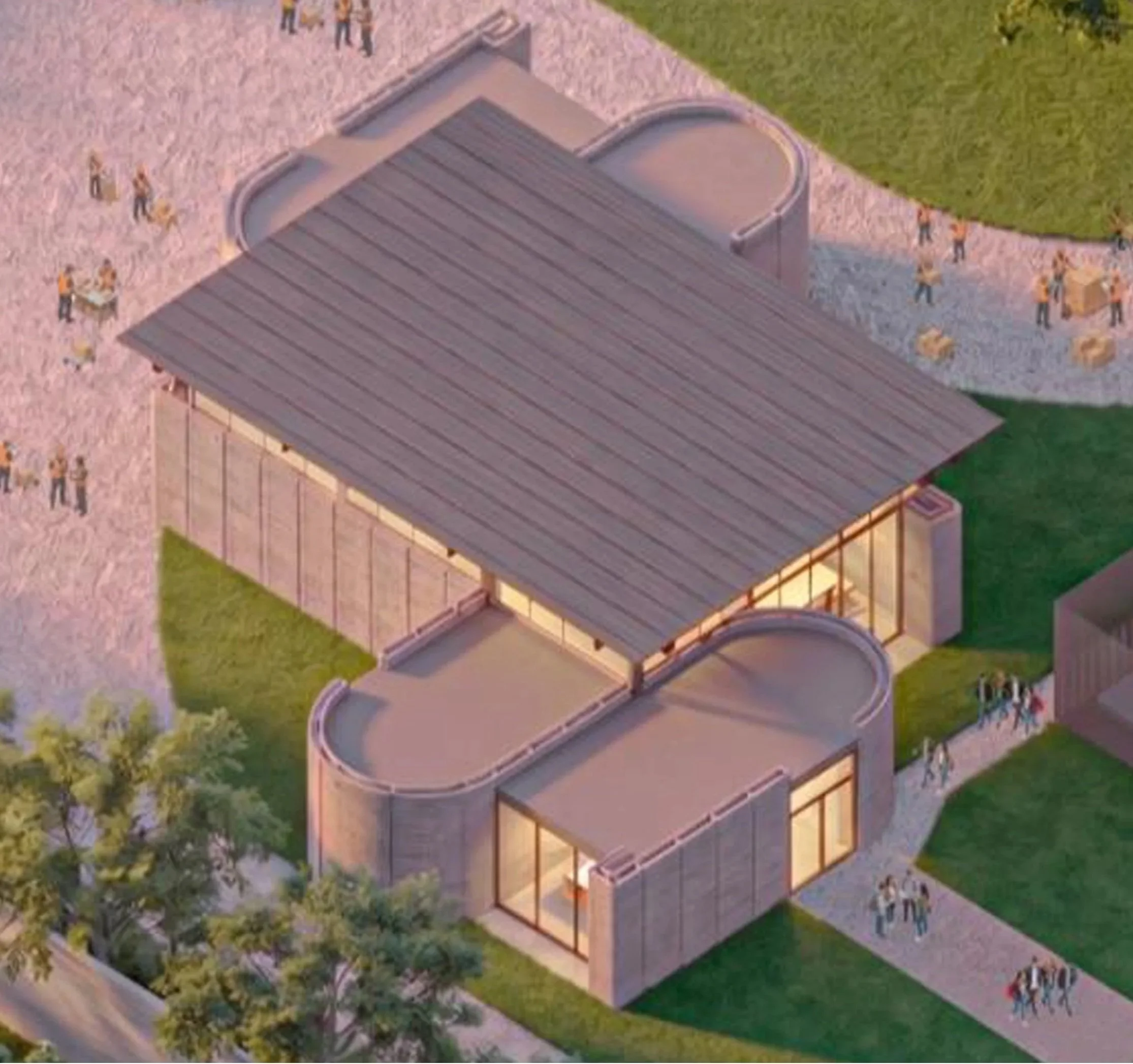
At the architectural scale, the project extends these validated principles into a full building proposal, represented through renderings that illustrate the application of the 3DPC wall system as a parametric and spatial framework (Fig. 8). The base planar wall configuration established during the design phase is combined with computationally generated geometric variations, enabling the exploration of curvature, orientation, and surface articulation within the constraints of the fabrication process.
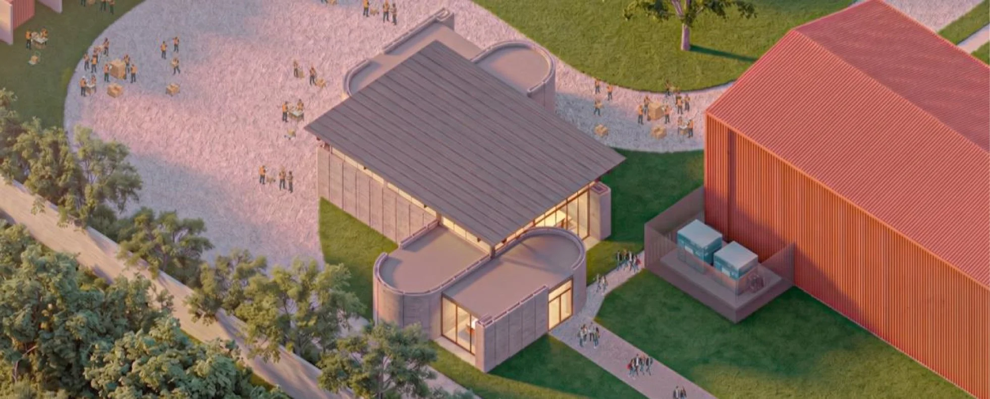
Figure 8. Final renderings of the proposed building, highlighting the 3D-printed wall system and its role in shaping spatial organization and architectural form. Renderings generated using artificial intelligence (Google Gemini).
Conclusion
Central to this exploration is the question of how to attain geometric freedom while complying with building regulations, structural requirements, and fabrication techniques. Rather than viewing these constraints as limitations, they are understood as fundamental components that shape and drive the design process. The research emphasizes the importance of aligning material behavior with geometric intent to create a cohesive design-to-fabrication pipeline and highlights the development of modular systems.
Gallery